CONTENTS
1. DESCRIPTION............................................................................ 2
1.1 Concept......................................................................................................... 2
1.2 General
Features..................................................................................... 2
1.3 Technical specifications..................................................................... 2
2. OVERVIEW................................................................................. 3
2.1 LCD Display................................................................................................... 3
2.2 Indicators..................................................................................................... 4
2.3 SILENCE button and ALERT key switch.............................................. 4
2.4 SIREN fuse..................................................................................................... 4
2.5 Internal audible alarm......................................................................... 4
3. INSTALLATION.......................................................................... 5
3.1 Power supply............................................................................................... 5
3.2 Alarms............................................................................................................ 5
3.3 Sensors........................................................................................................... 5
4. OPERATION............................................................................... 6
4.1 Detect and alarm..................................................................................... 6
4.2 Watch feature........................................................................................... 6
4.3 Program input status feature.......................................................... 6
5. WIRING SCHEMATICS............................................................. 8
1.0 Description
1.1 Concept
AP10-1/P Alarm Panel is a microcontroller alarm system designed for on board applications. The application of microprocessor techniques ensures low power consumption and high reliability of equipment.
• Up to 10 alarm circuits can be connected to each unit such as water level, smoke and heat detectors, plus other engine condition sensors.
• AP10-1/P is a self-contained alarm system with an LCD display indicating each alarm point. An alarm location is indicated by a text display on the LCD.
• Alert feature
(“Asleep at the Wheel” alarm) to keep the operator awake. When this function is enabled, the internal
buzzer will activate after a timing interval.
1.2 General Features
· 10 alarm circuits
· Optically isolated inputs
· Programmable input status
· Programmable alert interval time
· LCD display with back light
· Alert feature “Asleep at the Wheel” alarm to help keep the operator awake
· Audible disable switch
· Compact design with self-contained flasher and audible alarm
· Common alarm relay output (external alarm such as horn or flasher can be connected)
· Power input 12-36 VDC
· Bulk head or dash mountable
1.3 Technical specifications
Alarm Inputs Programmable
Outputs Siren contact: Max. 8A
Detectors power supply: 0.5A-12VDC
Indication LCD display with LED flasher
Alarm info Programmable
Flash Frequency 60 pulses/min.
Power Requirements 12-36 VDC
Current Consumption (Control unit only)
Standby: 80 mA
Alarm: 100mA
Operating Temperature 0-50C (32.0 – 122.F)
Storage temperature -20 – 70C (-4.0 – 158 F)
Terminals Screw terminals pluggable
2.0 Overview
The AP10-1/P alarm panel is simple to understand and operate.
On the front of the panel are the 16x2 LCD display, indicators, SILENCE pushbutton, siren fuse and ALERT set key switch. An alarm buzzer is built into the panel.

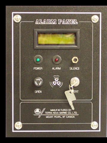
All wires on panel connecting to the PC board use quick connectors for easy installation and repair.
The AP10-1/P Alarm Panel has a watch function (“Asleep at the Wheel” alarm). You activate this function by turning on the ALERT switch and pushing the SILENCE button. The key can be removed to prevent unauthorized deactivation of the system.
2.1 LCD Display
At the top of the panel is a 2-line 16-character yellow backlight LCD display module.
The unit can be pre-programmed for language preference. The LCD displays an alarm type/location message and flashes when the unit detects alarm signals. It will continually display the message and flash until the alarm condition has been cleared. After the alarm condition has been corrected, the display can be cleared by pushing the SILENCE button.
When the ALERT function is activated, the LCD will display watch function status ENABLED or DISABLED.
2.2 Indicators
In the front of the panel, a green LED indicates if the unit is powered.
The center of the panel has a red LED indicating if an alarm has been detected.
2.3 SILENCE button and ALERT key switch
At the right of the panel, a pushbutton can silence the audible alarm after an alarm has been detected.
When the alarm condition has been cleared, pushing the SILENCE button will clear corresponding alarm messages on the LCD display.
Turning on the ALERT key switch and pushing the SILENCE button will enable or disable the watch feature.
2.4 SIREN fuse
In the front of the panel is a fuse used for the external siren circuit protection.
2.5 Internal audible alarm
In the center back of the panel, an audible alarm horn will activate when a new alarm condition is detected. It will keep alarming until the SILENCE button is pushed.
3.0 Installation
3.1 Power supply
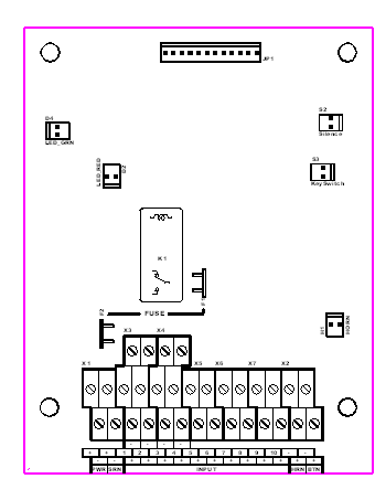
The power supply input leads connect into the double-level terminal block labelled PWR, with the polarity indicated.
3.2 Alarms
The internal alarm is located at the back of the panel. The sound exits a small hole at the center of the panel.
The external alarm (siren or flasher) can be connected via the double-level terminal block labelled SRN, with the polarity indicated.
3.3 Sensors
Two-wire sensors such as bilge switches, heat detectors or pressure sensors should be connected at the low and mid level of the triple-level terminal block, which is labelled INPUT (see Figure 3).

Sensors requiring power supply from the AP10-1/P panel, such as smoke detectors, should be installed at the third or top level terminal block. One pole of the relay on the smoke detector should be connected to positive and another pole connected into the mid-level terminal block (see Figure 4).
If the smoke detectors are supplied from another power source, the two poles of the relay on the sensors connect as two-wire sensors (see Figure 5).
4.0 Operation
4.1 Detect and alarm
When the system detects an alarm condition, the alarm message will display on the LCD, indicating where and what alarm has occurred. Also, the internal audible alarm will activate. After about one minute, the system will activate the external alarm if an operator does not press the SILENCE button after the alarm sounds.
Pressing the SILENCE button will silence both the internal and external audible alarms, but the alarm message will continue on the LCD display with the backlight flashing until the alarm condition is cleared and then pushing the SILENCE button.
4.2 Watch feature (“Asleep at the Wheel” alarm)
Turning on the key switch will entry the Alert Setup Menu. Pushing the SILENCE button will change the interval of the watch or disable the watch feature. Turning the key switch off will finish the Watch Feature Setup. The watch feature status you changed will be permanently stored in the unite memory.
The message [PUSH BTTN & TURN KEY ->SETUP INPUT] will display a short time on the LCD when you turn on the key switch. That message tell you how to enter the Setup Input Menu (See Program Input Status Feature).
The watch feature provides the enable 5, 10, 15, 20, 25, 30 minutes watch interval and disable watch feature. The default watch feature is enabled with 15-minuts intervals.
At the end of the watch interval, the internal buzzer will activate intermittently. The operator (helmsman) must press the SILENCE pushbutton before one minute. If not, the system will activate the external alarm to warn the other crewmembers. After pushing the SILENCE button, the watch interval will restart.
4.3 Program input status feature
Entry and exit
the Program input status menu:
Press the SILENCE pushbutton then turn key switch on, the unit will enter the setup input menu. Press the SILENCE pushbutton then turn key switch off (back) the unit will exit setup menu and store the setup data. The message [PUSH BTTN CHANGE RETURN KEY SET ] will appear shortly before entering the setup menu.
CH01
DELAY 3sec NORMALLY Close
Select terms
In the setup menu you can select channels, delay time and normally open/close terms by turning the key switch off then turn it on. The blink cursor will jump to each term and loop.
CH01 ® DELAY
3sec ® NORMALLY Close
____________________________________½
Change the term status
Pushing pushbutton can change the status where the cursor is located.
All channels status of the factory setup are normally closed and have three second delay.
Example:
Set channel six to normally open and six second delay time.
Step 1
CH01
DELAY 3sec NORMALLY Close
Press SILENCE button then turn key switch on
The LCD display should be like this.
CH06
DELAY 3sec NORMALLY Close
Step 2
Push the button five times, the LCD will display the
Channel six settings.
CH06
DELAY 3sec NORMALLY Close
Step 3
Turning the key will switch off (back) then turn on. The cursor jumps to delay term.
CH06
DELAY 6sec NORMALLY Close
Step 4
Pushing the button three times. The channel six delay time will set to three seconds.
CH06
DELAY 6sec NORMALLY Close
Step 5
Turning the key will switch off (back) then turn on. The cursor jump to normally close/open term.
CH06
DELAY 6sec NORMALLY Open
Step 6
Push the button. The normally close/open status will change to normally open.
CH06
DELAY 6sec NORMALLY Open
Step 7
Turning the key will switch off (back) then turn on. The cursor jump back to the channel term. If you want to set more channels repeat step two to step seven.
AP10-1/P
ALARM PANEL
Step 8
TERRA
NOVA MARIN
Pressing the button then turning the key will switch off (back) to finish setup. Now the channel six will work with normally open sensors and has a six second delay.
5.0 Wiring Schematics
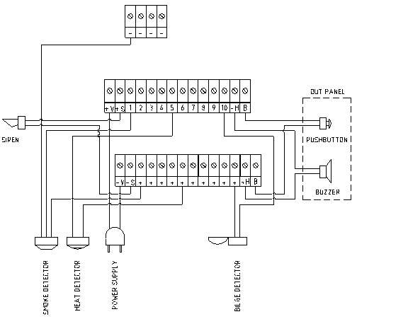
Figure 3: Schematic of Sample Wiring
Smoke detectors should be connected with terminal group 1,2,3 or 4. It has two optional wiring configurations as following:
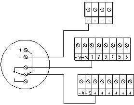
Figure 4: Example Wiring – Smoke Detector Powered by Panel
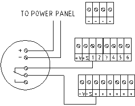
Figure 5: Example Wiring – Smoke Detector Powered by Vessel’s Main Power Supply